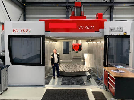
TRIMILL 6 Axis
Profile Milling Machine
Trimill Video links:
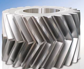
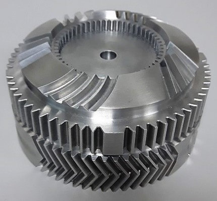
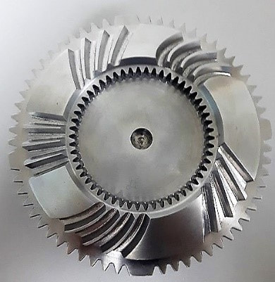
Spur, Spiral Bevel, Herringbone , Internal, Segment, Worm
Spiral Bevel being Cut by TRIMILL
Worm wheel - rough, finishing, cutting and measurement
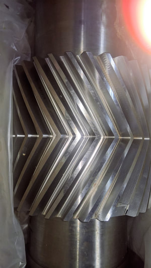
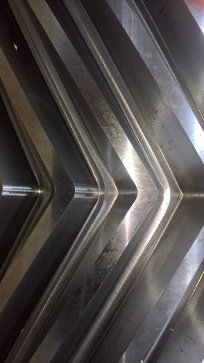
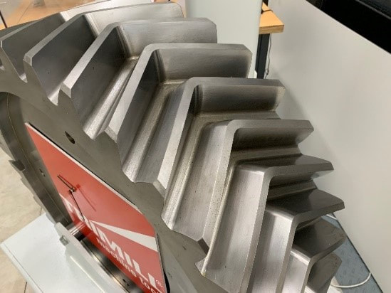
Herringbone Cutting
Trimill Application / Tooling
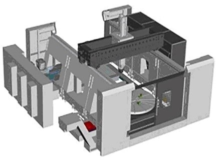
GANTRY-TYPE MULTI-FUNCTIONAL MACHINING CENTRE
Herringbone gears, All disciplines of Bevel Gears, Worm, gears, Helical. Spur gears with Modul 60 in the rough cutting mode and Finishing After heatreatment Hard cutting to 60 RC.
. And much more on one machine
In case of an enquiry we would like focus diameter
TRIMILL Gear Line VG 1600 – max. workpiece diameter 1.600 mm / 63 inch
TRIMILL Gear Line VG 2500 – max. workpiece diameter 2.500 mm / 98 inch
TRIMILL Gear Line VG 3000 – max. workpiece diameter 3.000 mm / 118 inch
TRIMILL Gear Line VG 4000 – max. workpiece diameter 4.000 mm / 157 inch
TRIMILL Gear Line VG 6000 – max. workpiece diameter 6.000 mm / 236 inch
-Complex machining
6 axis
-Utmost flexibility
-High dynamics and cutting power
-Long-lasting high accuracy
-Maximize productive times
-Direct measuring in all axes
ACCURACY DIN 3-4
AGMA 12 11 10 9 8
DIN 1 2 3 4 5 6 7 8
Video: Spur, Spiral Bevel, Herringbone , Internal, Segment, Worm
Trimill Video links:
Spur, Spiral Bevel, Herringbone , Internal, Segment, Worm
Spiral Bevel being Cut by TRIMILL
Worm wheel - rough, finishing, cutting and measurement
Herringbone Cutting
Trimill Application / Tooling
Profile Milling Machine
Trimill Video links:
Spur, Spiral Bevel, Herringbone , Internal, Segment, Worm
Spiral Bevel being Cut by TRIMILL
Worm wheel - rough, finishing, cutting and measurement
Herringbone Cutting
Trimill Application / Tooling
GANTRY-TYPE MULTI-FUNCTIONAL MACHINING CENTRE
Herringbone gears, All disciplines of Bevel Gears, Worm, gears, Helical. Spur gears with Modul 60 in the rough cutting mode and Finishing After heatreatment Hard cutting to 60 RC.
. And much more on one machine
In case of an enquiry we would like focus diameter
TRIMILL Gear Line VG 1600 – max. workpiece diameter 1.600 mm / 63 inch
TRIMILL Gear Line VG 2500 – max. workpiece diameter 2.500 mm / 98 inch
TRIMILL Gear Line VG 3000 – max. workpiece diameter 3.000 mm / 118 inch
TRIMILL Gear Line VG 4000 – max. workpiece diameter 4.000 mm / 157 inch
TRIMILL Gear Line VG 6000 – max. workpiece diameter 6.000 mm / 236 inch
-Complex machining
6 axis
-Utmost flexibility
-High dynamics and cutting power
-Long-lasting high accuracy
-Maximize productive times
-Direct measuring in all axes
ACCURACY DIN 3-4
AGMA 12 11 10 9 8
DIN 1 2 3 4 5 6 7 8
Video: Spur, Spiral Bevel, Herringbone , Internal, Segment, Worm
Trimill Video links:
Spur, Spiral Bevel, Herringbone , Internal, Segment, Worm
Spiral Bevel being Cut by TRIMILL
Worm wheel - rough, finishing, cutting and measurement
Herringbone Cutting
Trimill Application / Tooling
6 AXIS GEAR PROFILE MILLING
Gears Discipline’s: Herringbone, Bevel, Spiral Bevels, Helical, Spur, Worm, Internal, Etc.
Gears Discipline’s: Herringbone, Bevel, Spiral Bevels, Helical, Spur, Worm, Internal, Etc.
|
|


Powered by GWJ Software Technology Package
Videos links:
https://youtu.be/ZUdik3Hvh58
https://youtu.be/yS12dZmp62w
https://youtu.be/ug7fjqlaQEo
Download the GearEngineer manual via the following link:
https://www.gwj.de/fileadmin/dokumente_web/gwj/GearEngineerHandb_en.pdf

Overview and detailed information on GWJ Software Package:
Standard Calculation Software for Machine Elements
• eAssistant: Web-based calculation software for machine elements
• TBK: Software for gear design & mechanical engineering
• CAD plugins: eAssistant/TBK CAD plugins for 3D CAD systems
• Gear Engineer: Real 3D tooth form & more for alternative manufacturing
Bevel Gear
The tooth form of bevel gears is slightly modified from the involute tooth form of cylindrical gears. The bevel gear follows the octoid tooth form. This tooth form is similar but not identical to the involute tooth form on cylindrical gears.
Octoidal Tooth Profile
Some software solutions determine a simplified 3D bevel gear geometry based on a virtual spur gear to approximate the profile of a bevel gear. This technique assumes that the tooth form of a bevel gear follows an involute as a tooth form and not an octoidal tooth profile.
● Simplified calculated bevel gears on the basis of a virtual spur gear in normal plane with an involute tooth form show a deviant tooth form with reduced root strength by 10% to 28% without offset and 45% with offset [Diss. Huenecke, TU Dresden].
● Lower tooth root strength results from differences in the tooth profile (for example tooth root thickness, bending moment arm, root radius at 30° tangent).
The tooth contact pattern of real spiral bevel gears with an octoidal tooth profile is usually shaped as a parallelogram manufactured on Bevel machines, bevel gears manufactured on 5-axis machining centers and bevel gears produced on Bevel machines can be meshed.
Manufacturing of:
3D solid model with arbitrary number of teeth in STEP/IGES format
● 3D surface model of tooth space width in STEP/IGES format
● Gear body without teeth as 3D model in STEP/IGES format
● Curves to support programmed milling strategies
TBK Manufacturing Suite allows with the TCA tooth contact analysis a calculation and simulation of the contact pattern on the gear and pinion. This calculation simulation can be compared similarly to a rolling test on a rolling tester. TCA is available for all gear types.
Gears are automatically checked for collisions and interferences.
● A CAM solution, capable for simultaneous 5-axis operations, is required for programming the machining center including the machining strategy.
● 5-axis simultaneous milling is required for helical cylindrical gears and also for helical and spiral bevel gears.
● Various CAM solutions are available on the market. Is a 5-axis simultaneous CAM system already available, it is possible to use this also for 5-axis milling of gears.
General Concept: Workflow of 5-Axis Milling Process
Gear Software: Gear Engineer
Provision of real 3D geometry of gearings as basis for alternative manufacturing methods
The Gear Engineer is a powerful software for the calculation of the real 3D geometry of gearings. This geometry provides the basis to manufacture cylindrical and bevel gears in conjunction with multi-axis machining centers. The Gear Engineer is one of the world´s leading and award-winning software products in this field.
Gear Software: Background Information
Gear Tooth Form ≠ Gear Tooth Form
● Correct gear tooth geometry is essential for five-axis milling.
● The purpose of gears is to transmit motion and torque. That means that load capacity and running behavior of five-axis milled gears need to be identical to conventionally manufactured Gears
● The gear tooth form for five-axis milling should be identical to conventionally manufactured gear
Cylindrical Gears
● Mathematical simulation of the manufacturing process provides the real tooth form geometry of root and flank.
● CAM programming: Flank and root geometry including the transition between root curve and flank must be very precise 5-axis simultaneous machining makes it possible
